GAS FILLED UNITS
Why filling gas?
The purpose of gas filling is typically to reduce the heat transfer and improve the energy efficiency of the insulating glass unit. Gas filling can also be a means of reducing the sound transfer through an insulating glass unit and improving the acoustical properties.
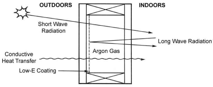
Heat is transferred through insulating units via radiation, conductive or convective heat transfer routes. The use of low-E (low-emissivity) coatings has dramatically improved the radiation heat transfer through glass by selectively allowing only some types (or wavelengths) of radiation to pass. See Figure 1. The theory behind the low-E coatings is well documented in published literature.
WHAT ARE THE BENEFITS?
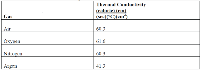
The use of gas filling further improves insulating glass unit heat transfer by reducing the conductive heat transfer. This is accomplished by the use of gases having lower thermal conductivities than air. (Air is approximately 79 percent nitrogen, 21 percent oxygen.) The gases typically used are argon, for heat transfer reasons, and sulfur hexifluoroide (SF6), for acoustic purposes. A comparison of relative gas thermal conductivities9 is shown in Table I.
TABLE I: Gas Thermal Conductivity
IMPROVMENT
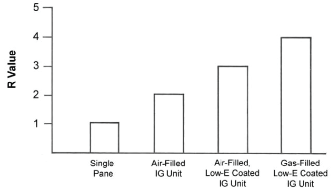
How much can gas filling improve the energy efficiency of an insulating glass unit? A comparison of Rvalues for various glazing combinations is shown in Figure 2. A single-pane window has an R-value of approximately 1. By going to a non-coated, air-filled dual pane insulating glass unit, the R-value is increased to approximately 2. Adding a low-E coating to the insulating glass unit increases the R-value to approximately 3. Finally, by gas filling the coated insulating glass unit, the R-value can be raised to approximately 4.FIGURE 2
GAS FILLING EQUIPMENT
The two current methods for gas filling include the vacuum method and the probe method. Each requires state-of-the-art equipment, and each has its own unique advantages and disadvantages.
In the vacuum (or chamber) method, the insulating glass units are initially evacuated and then backfilled with the inert gas of choice. The units are placed in some form of chamber and evacuated. The chamber, and hence the units, are then backfilled with the gas of choice. The efficiency of gas filling by this method depends on the number of units that can fit into a chamber, as well as the speed at which the chamber can be evacuated and backfilled with gas. Some insulating glass unit manufacturers hold patents on and utilize this method.
An alternative method to the vacuum method is the probe (or lance) method. The general intent of this method is to fill the insulating glass units with gas via one lance or probe, while evaluating the exiting air via a second lance location. When the exiting samples contain a high concentration of the inert gas, as tested by a gas chromatograph, the units are assumed to be fully filled.
The locations of the lances or probes vary, depending upon unit size and fabrication processes. Both probes can be placed along one vertical side, along the top, at diagonal corners, or one along a vertical side with the other at the top. These are just a few of the probe location combinations possible. The location combination affects the filling efficiency, so you should work with your gas-filling equipment supplier to determine the most efficient locations for your production.
Once the sensor indicates that the units are filled with gas, the probes are removed, the holes immediately filled with polyisobutylene (PIB), and any final sealing performed. Care must be taken to prevent the gas from entering the unit so fast that turbulence occurs in the unit, as this could give inaccurate sensor sample evaluations and filling efficiency predictions.
Gas-filling equipment for the probe method is available from several suppliers, including Ratio Technik, Pector, and Lisec. A more detailed description of the probe method and its advantages and disadvantages is available from these equipment suppliers.
APPLICATION RECOMMENDATIONS
Several factors, including unit design and workmanship, affect the success of gas filling your insulating glass units.DESIGN
Your insulating glass unit design affects the success of your gas-filled insulating glass units. The loss of gas can be reduced by increasing the resistance to gas leakage. Gas leakage can be slowed by decreasing the area available for gas transmission and increasing the path length required for gas transmission.WORKMANSHIP
Workmanship plays an important role in determining the success of gas filling, much as it does in ensuring success of manufacturing a normal air-filled insulating glass unit. Your glass lites and spacers must be properly cleaned to ensure that the primary and secondary sealants attain satisfactory adhesion. Improperly cleaned insulating glass units, regardless of sealant choice, can potentially have premature failure and gas loss due to sealant adhesion failure.
Spacers must be properly aligned. Failure to do so will result in less than desired secondary seal depths. PIB primary seal stressing and failure can occur if insufficient secondary seal is present to maintain unit structural integrity.
Bent corners are typically used to maintain a solid, uniform spacer. Corner keys and any probe holes located in the spacer should be butyl injected to eliminate voids or openings of any kind through which gas could migrate.
Any voids or openings will act as open doors through which the gas will migrate with minimal resistance.
It is essential that you have a uniform, consistent primary seal. The seal cannot contain voids or skips. Any voids or skips will also act as open doors for gas migration.
The secondary seal must also be free of voids or skips. Any inconsistencies may allow undue stressing or failure of the PIB seal, the primary barrier to gas leakage. Two-part sealants must be properly mixed and used at the proper mix ratio.
The initial efficiency of your insulating glass units will also affect the long-term performance of your units. In simplistic terms, the more inert the gas you use to fill your units, the higher the R-value of the units.
Secondary Sealant Selection
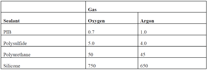
If you consider the permeabilities of the individual secondary sealants, you will notice a large difference between the sealant families. See Table V. Polyisobutylene is the least permeable to oxygen, nitrogen, and argon. Polysulfides have the next lowest permeabilities, followed by the polyurethanes. Silicone sealants are the most permeable of the common sealant families.TABLE II: Sealant Permeabilities Gas
The key to choosing the proper sealants, though, is to focus on the gas leakage through the insulating glass unit as a whole, not necessarily through individual components. A properly applied polyisobutylene (PIB) primary seal is so impermeable to inert gases that it will act as the main barrier to prevent the inert gas from leaking. The secondary seal then becomes the adhesive that holds that unit together and protects the primary seal from harsh environmental conditions and premature degradation.
Silicone sealants have superior performance in regards to maintaining adhesion, tensile strength, and flexibility after exposure to ultraviolet radiation, water immersion, temperature extremes, and stressing when compared to their organic counterparts. So, although silicone sealants may have relatively high gas permeation rates, when used in combination with a low permeability polyisobutylene (PIB) primary seal, these dual seal silicone insulating glass units have proven to retain inert gas exceptionally well. Field testing of argon-filled insulating glass units by Cardinal IG shows a 97 percent argon retention after over 2-1/2 years of aging.
Industry Testing for IG Unit Gas Leakage
The test methods used in Europe to determine gas leakage rates out of insulating glass units are the DIN1286 Part 2 and 52 983 test methods. In essence, the edge of an insulating glass unit is captured in a metal channel of a given control volume. The control volume is initially purged with helium. The unit is then maintained in this condition for a given time period. After the specified aging time, a sample of the gas in the control volume is extracted, separated, and analyzed for gas concentrations. By determining the gas concentrations in the control volume, the gas leakage rate out of the insulating glass unit can, in theory, be approximated and extrapolated for the unit’s lifetime.
The test does require a short time period, so testing can be done quite rapidly to determine the rate of gas leakage out of an insulating glass unit. Unfortunately, the short time period and potential for experimental error in the helium purge can result in high errors when extrapolating data for expected gas leakage rates over many years.