Open
the fuel pump file in Maya which
was saved in the previous part of the tutorial.
Open Maya
Step 2
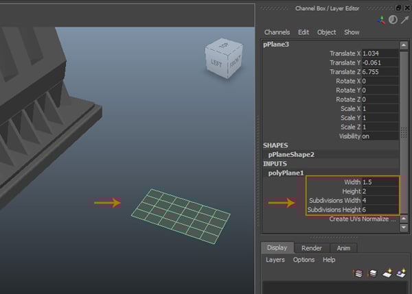
To model the
fuel nozzle, create a pPlane with Subdivisions Width as 4, Subdivisions Height as 6, Width as 1.5 and Height as 2.
Creating a plane
Step 3
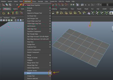
With the
five edges selected, go to Edit Mesh
>Bevel and click on option
box.
Edit Mesh > Bevel
Step 4
In the Bevel Options window, keep the values
of Width as 0.2000, Segments as 2. Click on Bevel button.
Bevel Options
You can see
the offset edges with the main edges.
offset edges
Step 5
With
all in-between edges selected, go to Edit
Mesh>Delete Edge/Vertex command.
Edit Mesh > Delete Edge/Vertex command
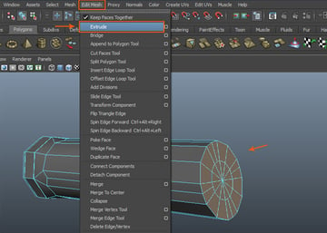
Step 6
With the
indicated faces selected, go to Edit Mesh
>Extrude command.
Edit Mesh > Extrude
Step 7
After
applying the extrude command, drag the faces downwards a little bit.
Drag the faces downwards
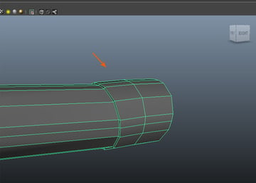
Step 8
With the
left - right border edges selected, extrude these outwards a little bit.
Extrude
Step 9
Follow the
same procedure with the rest border edges also.
Follow the same procedure
Step 10
Turn on Animation mode. With the mesh selected,
go to Create Deformers >Nonlinear >Bend command.
Create Deformers > Nonlinear > Bend
Step 11
After
applying the Bend deformer, you can see a wire object placed vertically.
Bend
Step 12
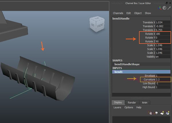
Rotate the
wire in the 180 degree angle in X axis.
Rotate the wire
Step 13
Keep the Rotate Z value as 90 and Curvature as 2.2.
Rotate the wire
Step 14
After
bending the poly mesh, go to Edit >Delete by Type > History command to delete the history.
Edit > Delete by Type > History
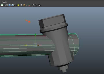
Step 15
Place the pump
holder model at the left side of the fuel pump.
Holder placement
Step 16
With the
indicated edges selected, extrude and drag them up a little bit.
Extrude and drag
Step 17
Extrude the
faces a little bit to add some thickness.
Extrude the faces
Step 18
Insert
several supporting edges and edit them to complete the holder.
Insert several supporting edges
2. Modeling Bolt for Connecting Pump Holder
Step 1
In the Polygons mode, click on cylinder icon
and create a small cylindrical shape in the viewport.
Polygons mode
Step 2
Set the values
of Subdivisions Axis as 6, Subdivisions Height as 1
and Subdivisions Caps as 2.
Set the values
Step 3
Place this
hexagonal nut at the indicated place.
Place this hexagonal nut at the indicated place
Make another
copy of the nut and place it at the other side as well.
Make another copy
3. Creating Hand Pump
Step 1
Create a
polygon cylinder with the settings as shown under INPUT node in Channel Box/
Layer Editor.
INPUT node
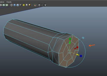
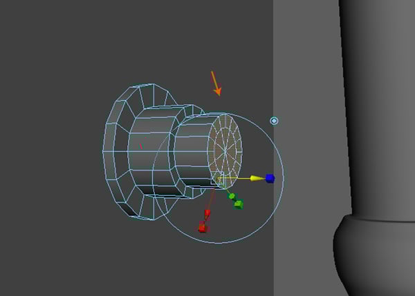
Step 2
With the cap
faces of the cylinder selected, go to Edit
Mesh >Extrude command.
Edit Mesh > Extrude
Step 3
Scale up the
extruded faces a bit outwards.
Scale up the extruded faces
Step 4
Press F9 key for vertex selection mode. With
the two indicated vertices selected, go to Edit
Mesh >Merge command to weld the
selected vertices.
Edit Mesh > Merge
Step 5
Following
the same procedure, select and weld each two alternate vertices together as
shown in the following image.
Merge the vertices
Step 6
Merge the
triangular faces also.
Merge the triangular faces
Step 7
For reducing
the unwanted edges, select every alternate edges and delete them all.
Reduce the unwanted edges
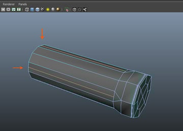
Step 8
With all cap
faces selected, extrude once.
Extrude cap faces
Step 9
Keep
extruding and editing the faces to get something like this.
Keep extruding and editing the faces
Step 10
Insert an
edge loop as shown in the following image.
Insert an edge loop
Step 11
Following
the same way, insert edge loops around all triangular faces.
Insert edge loops
Step 12
To make the
hand grip better, insert several more edge loops around the hand grip area.
Insert edge loops
4. Creating Fuel Controller Chamber
Step 1
For modeling
the fuel controller chamber, duplicate the grip model polygon mesh and rotate
it about 80 degree as shown in the
following image.
Duplicate the grip model
Step 2
Select the
rig faces as shown in the following image.
Select the rig faces
Step 3
Extrude and
scale down the selected faces.
Extrude and scale down the selected faces
Step 4
Extrude the
same faces once more and edit the edges as indicated in the image below.
Extrude the same faces
Step 5
Select and delete the
bottom faces of the mesh.
Delete the bottom faces
Step 6
With the
border edges selected, extrude and scale down a bit as shown in the following
image.
Extrude and scale down
Step 7
Keep
extruding and editing the edges until you get the shape as shown below. With
the last border edges selected, go to Mesh
>Fill Hole command to fill the
empty space.
Mesh > Fill Hole
Step 8
Insert two
edge loops as indicated in the image below.
Insert two edge loops
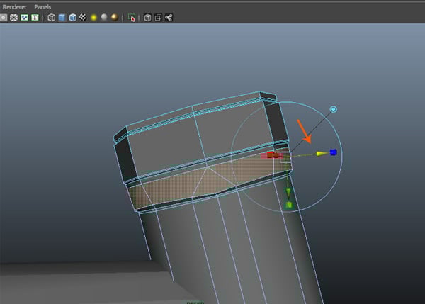
Step 9
With the
indicated face loop selected, extrude and scale down a little bit.
Extrude and scale down
5. Finishing Hand Pump Section
Step 1
After
finishing the fuel controller chamber, it’s time to complete the hand pump
section. With the handle grip polygon mesh selected, go to Show > Isolate Select>
View Selected and turn on the check box.
Show > Isolate Select > View Selected
Step 2
Rotate the
indicated border vertices around 25 degree
in X axis.
Rotate the indicated border vertices
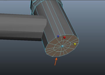
Step 3
With the cap
faces selected, go to Edit Mesh >
Extrude command to extrude the selected faces.
Edit Mesh > Extrude
Step 4
Keep extruding
and sculpting the shape as shown in the following image.
Keep extruding and sculpting the shape
Step 5
Unhide the
hidden meshes, so you could model the objects seeing all parts of the mesh.
Unhide the hidden meshes
Step 6
Extrude thrice
the end part of the object to make it like the injector pipe holder.
Extrude thrice
Step 7
The hand
pump section is completed now.
The hand pump section completes
6. Creating Handle and Trigger
Step 1
Create a
polycube.
Create a polycube
Step 2
Extrude the
top and bottom faces as shown in the following image.
Extrude the top and bottom faces
Step 3
Keep
extruding and editing the bottom face and form the indicated shape as shown in
the following image.
Keep extruding and editing
Step 4
Select the
inner faces.
Select the inner faces
Step 5
Extrude and scale
down the faces a little bit.
Extrude and scale down the faces
With the
indicated faces selected, press G
key to repeat the previous extrude command.
Press G key
Step 6
Select a
face as indicated in the image.
Select a face
Step 7
Extrude the
selected face thrice.
Extrude the selected face
Step 8
Continue
extruding and editing the face to make it as a trigger as shown in the
following image.
Continue extruding and editing
Step 9
To add details,
select the two faces at either sides and extrude a little bit.
Add details
7. Suspension Spring Modeling
Step 1
Go to Create >Polygon Primitives>Helix command.
Create > Polygon Primitives > Helix
With the Helix tool, create a helix polygon
object in the perspective viewport.
Helix tool
Step 2
Set the
parameters of the helix as shown in the INPUTS
channels. Place the helix shape around the pipe as shown in the following
image.
INPUTS channels
Step 3
With the all
hand pump parts selected, go to Edit
>Group command to make a group
of the selected meshes.
Edit > Group
Step 4
After making
the group, go to Modify >Center Pivot command to center the
pivot of the grouped object.
Modify > Center Pivot
Step 5
Put this
hand pump model inside the pump holder.
Put this hand pump model inside the pump holder
8. Creating Rubber Pipe Connector
Step 1
Create a polygon
cylinder in the side view.
Create a polygon cylinder
Step 2
Keep the
values of Subdivision Axis as 16, Subdivision Height as 1 and
Subdivision Caps as 3.
INPUT Channel
Step 3
With each
alternate central edges selected, press Delete
key to delete them all.
Press Delete key
Step 4
With the
indicated faces selected, go to Edit
Mesh > Extrude command to extrude selected faces.
Edit Mesh > Extrude
Step 5
Keep
extruding and editing the faces to make something like this.
Keep extruding and editing
Step 6
Go to Create>CV Curve Tool and
click on its options box. In the Tool Settings
window, turn on 3 Cubic radio button.
Create > CV Curve Tool
Step 7
In the front
view, start creating the curve from the rubber pipe connecter to downwards.
Start creating the curve
Step 8
Complete drawing
the curve line for the rubber pipe model as shown in the following image.
The rubber pipe model
Step 9
Edit and
arrange the vertices of the pipe something like this.
Edit and arrange the vertices
Step 10
First select
the indicated faces of the rubber connector and then with pressing Shift key, select the CV curve also. Go
to Edit Mesh >Extrude command.
Edit Mesh > Extrude
Step 11
At first, it
will only extrude the mesh from start to end. You need to increase the extrude
subdivisions.
Extrude subdivisions
Step 12
With the
extruded mesh selected, go to INPUT section
and increase the Divisions to 75.
INPUT section
Step 13
You might
have to edit the starting part of the pipe to make it look better.
Edit the pipe
Step 14
Create a small
cylinder with Subdivision Axis as 6.
Create a nut
Step 15
Put this nut
object above the base plate as shown in the following image.
Create a nut
Step 16
Do it for
all corners of the base plate.
Nut at all corners
Step 17
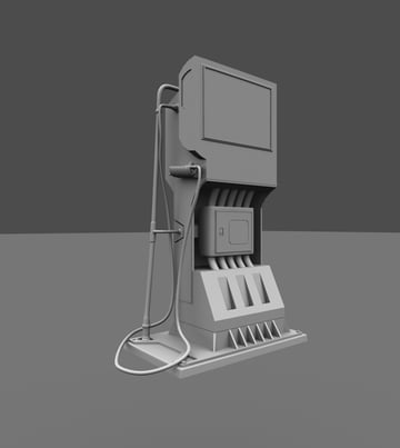
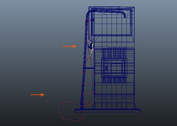
The fuel
pump modeling is completed now. In the next part, I will start unwrapping UVs
for texture map.
Complete model
The wireframe look.
Wireframe look
Conclusion
The modeling of the fuel pump is done. I hope you must have enjoyed the modeling session. In the next part of the tutorial, I’ll start unwrapping.
Subscribe below and we’ll send you a weekly email summary of all new Design & Illustration tutorials. Never miss out on learning about the next big thing.