DSC01187

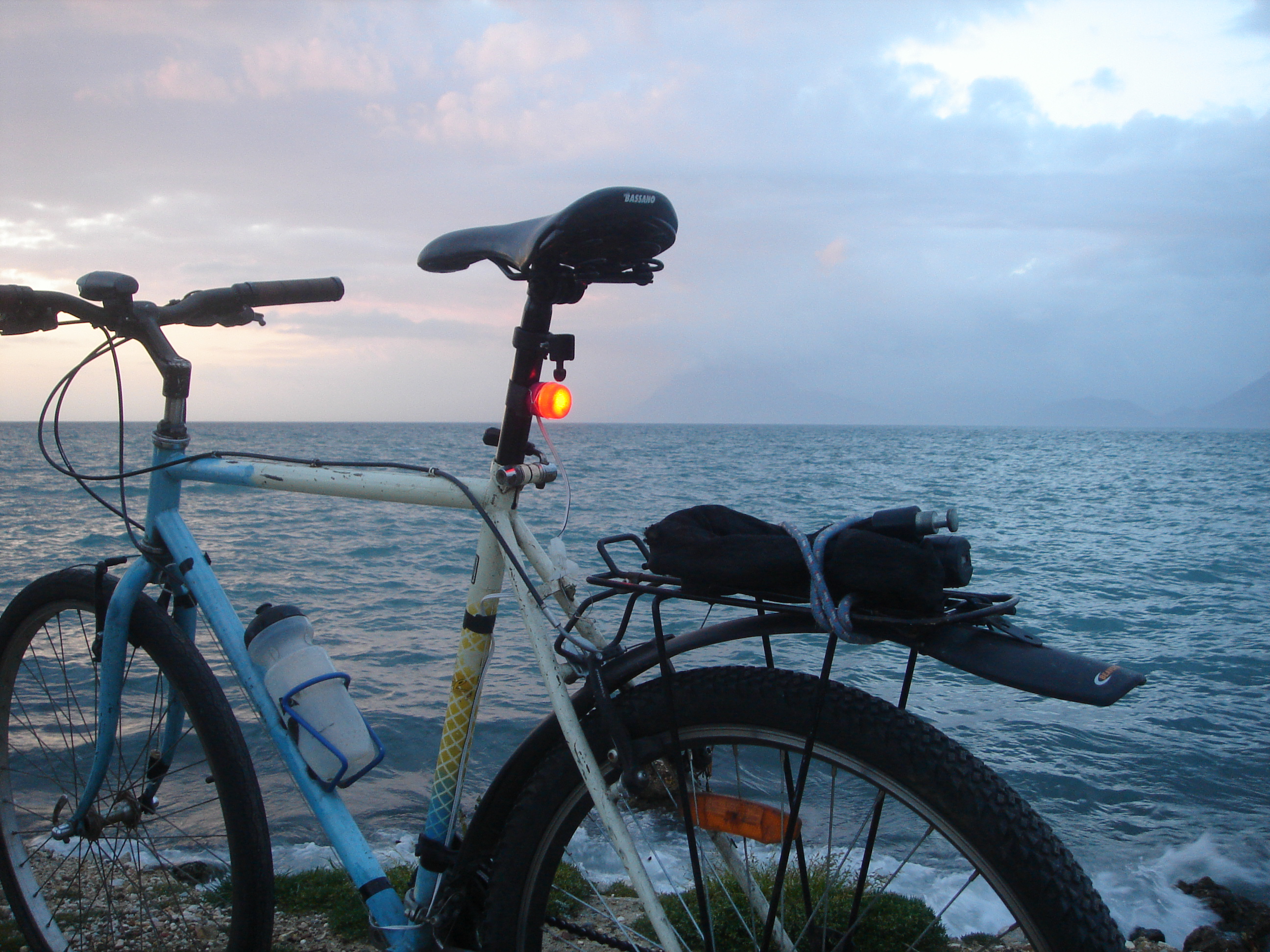
This automatic bicycle light from recycled and found parts is about the most eco-friendly DIY bike light in the world. It uses an LED placed inside a plastic bottle cap, which activates when a magnet mounted on the wheel passes a sensor, similar to how a bicycle computer works.

If the LED is bright, it will shine through the cap, so choose an orange or red cap for a tail light.

YouTube player

Project Steps

Prepare the Casing

First, scavenge two bottles (ideally from the same brand) from the trash. It doesn’t matter if the bottle is dirty, crushed, or destroyed as long as the part near the cap is intact.

Use a good razor to cut away most of the bottle and leave the part near the cap. Then put the cap on a piece of paper and draw a circle around it. That’s the circumference of the cap. Use that as a reference for your bottle so you know how much you should cut.

You’ll want the cap to fit snugly, so regularly check to make sure the cap fits on the open part of the bottle you just cut.

Fit the Cap on the Bottle

If the new cap fits, but it doesn’t sit perfectly, use a butter knife to open it. Then, with the razor, carefully remove some more plastic from the bottle and try again. It should make some nice clicking sounds as you press them more and more together.

Cut a piece off an average elastic band big enough to go all the way around the channel of the cap. Both the cap and the band should be completely dry. Make it sit right with a screwdriver and at the end make it overlap like you see in the pic. Then close the cap.

This stage is a bit of an overkill as even without it the lights will be waterproof, but it’s easy and it will make it impossible for the rain to seep in, so we will do it.

Finish the casing

Cut off the plastic ring in the middle. We need this part to be transparent plastic so the light can be seen from 360 degrees.

Use sandpaper or a Dremel to scrape off the logo of the company. Don’t overdo it!

Cut a plastic frame to hold the electronics

Now the interesting part begins. We will use some plastic from the remaining body of the bottle to create a little skeleton frame that’s going to hold the electronics.

Cut 2 strips the width of the cap and maybe a little more. They’ll work like a spring to hold the base of the LED in place.

Using the razor, cut the shapes shown in the first photo here. An alternative, easier pattern is one I’ve drawn on the right upper corner of the image. It’s not as stable, but it still works.

Place the male into the female and vice versa so you can hold it like in the second picture. Cut a slit in the middle of the 2 plastic strips with the razor and as you squeeze them together slide in an extra bit of plastic. That will be the base where the LED will sit. It should be longer than the diameter of the cap or it won’t fit.

Now, as you squeeze them together, put the skeleton right inside the casing and push it with your finger until it sits on the back of the cap.

Place the LED

Now that you see how it fits, take it out again and slide off the plastic base. Make a hole in the middle as big as the round lens of the LED. We want the lens to protrude from the other side. Make two little holes (more like two little slits) with the razor so the little ears of the LED can slide into to the other side, where we reconnect the resistor and the cable.

Seat the LED on the base facing the cap (so it’s upside down). Use a pair of needle nose pliers to straighten and then bend its little metal ears downward. Then, place it on the hole so its lens protrudes from the other side and make the metal ears go through the holes to the other side.

Flip the base over so you can see the metal ears. Use needle-nose pliers to connect the resistor to the negative side (you can see a little minus) and a piece of cable to the other one. Take a look at the pic for an example.

Put it inside the case! Push it with your finger until it goes all the way to the bottom.

Prepare and Place the Battery

From an aluminum can, cut out two discs the size of the cap. Use sandpaper or a Dremel to scrap off the plastic layer from the side of the disc (just one side).

Sketch with a pencil the shape of the plastic skeleton and drill four holes just outside it (see picture). Run a naked piece of cable through, like in the pic, and connect it with the end of the resistor by twisting them together. The twisted parts should be placed in the space outside the plastic skeleton, but inside the cap. The exposed cable on circular aluminum should face the battery that will be placed above.

Lay the coin cell on top of the disc. Make an identical aluminum disc that goes above the battery. Cut off a small piece on the edge of the disc for the cable that runs out from the bottom.

Run the Wires and Test It

Cut out a circular piece of inner tube that will fit snug above the aluminum disc.

Connect those two cables (green) with the two ends of another piece of wire (white) that will go through the cap. Just twist the ends together and add some tape. To test if your circuit works, touch the two ends of the cable together — the LED should light up.

Complete the Casing

Make a hole in the middle of the back cap. If possible, make it as big as the cable and similarly shaped. Run the cable through it.

Screw the cap tightly. Then, open it and see where the cable has marks from bending. Now, cut a small piece of inner tube (shape shown in the pic), stretch its smaller edge, and wrap it very tightly (clockwise, so when you screw in the cap it will tighten it more) around the cable 1 cm away from the bending mark and hold it there with your finger. Then take the cap and slide it over the inner tube part. This shape of the tube makes it slide more easily through the hole, and as you pull the cable the back part sticks in the hole, giving a waterproof seal.

Before you screw in the cap, you want to turn it counterclockwise one and a half rotations so the cables inside won’t twist so much!

Build the Sensor

Leave the light aside for a moment to start making the sensor.

First, cut a piece of a stick. Its width depends on the distance between your sensor and your magnet. If you want to put it on the fork, the distance is small so you need a thinner stick. If you want to place it on the back triangle the distance is greater, so you need a thicker stick.

When you find one, cut it a few centimeters longer than your reed switch. Then, drill a hole (big enough so the twisted cable can go through) all the way through the stick, lengthwise, somewhat near the edge.

Now, we will use a big piece of the cable (from the same stock we used to go through the cap) . This will connect the light with the sensor. Use needle nose pliers to hold the reed switch so you can twist its end together with one end of the cables (without pliers you will break it instantly). Slide it through the hole in the stick until it comes out the other end. When it does, twist it together with the other end of your cable. For extra security, you can use some tape to stick the two cable inside the holes.

Place the magnet close to the wood. When the wires are connected, the LED should light up.

Light Mounting Mechanism, Part 1

Take the wire and make a set of loops. Again, needle nose pliers are an essential tool for shaping the wire, especially if it’s a rustproof one. Notice that the one side has two loops: one for the strap and one for the hook.

Don’t get frustrated. This stage is a bit tricky in the beginning, but you will catch on quickly. You can also experiment and come up with a better inner tube holder.

NOTE: The wire loops shouldn’t extend beyond the height of the cap as I did in the pics. Also, when you complete this step, try the light on the seatpost and bend the loops slightly if the light doesn’t sit nicely.

Cut a strip from an inner tube and run it through the loops like a belt. We do it this way so we can adjust it later if we want to strap it on bigger or thinner tubes.

Light Mounting Mechanism, Part 2

Make a hook with the wire and strap it on the end of the inner tube strip. Bend a piece of wire on the folded end and press very hard until the hook is secure.

Connect the Light to the Sensor

Connect the wire ends with Tamiya connectors (or any other connectors you like — there are smaller and better-looking connectors on the market than the ones I used) . This connector is your on/off switch for when you don’t need the light (i.e. during the day).

Install

For the sensor to close the circuit every time the wheel spins, we have to put a magnet close to it. I chose a simple, discreet, and effective installation, but if you find a better one, let me know in the comments.

Cut a small piece of inner tube and roll the magnet up. Find the point where two spokes meet and wrap the tube and magnet around. Take a small piece of wire and bend it around the tube and two spokes. Turn it around until it’s comfortable for you to work on and clamp it down with pliers (as we did for the strap hook). Use scissors to cut off the remaining inner tube. Finally, turn it around until the magnet faces the sensor, and push it down until it is secure.

Now, cut a piece of the inner tube and put your sensor inside it. Then fold the excess rubber and put it on the fork or triangle. Use some zip ties (ideally reusable) to hold it in place. Use some more zip ties (don’t use many, just a few on places where the cable changes direction) to route the cable all the way to the seat post. Make sure the cable is discreet: under and behind the frame.

Now, strap the light on the seatpost. It’s very easy to hook and unhook it with your nail/finger.