Resolving the Signal Part 7: The Effects of Amplifier Noise on Delta-Sigma ADCs
This 12-part article series focuses on the impact of noise in delta-sigma ADCs. Part 7 shows how to analyze different amplifiers' effect on the noise of the same ADC.
This 12-part article series focuses on the impact of noise in delta-sigma ADCs. Part 7 shows how to analyze different amplifiers' effect on the noise of the same ADC.
In part 6 of “Resolving the Signal,” I defined output- and input-referred noise, derived equations for each, delved into single- and multistage amplifier configurations, and discussed the effects of increasing gain on low- and high-resolution analog-to-digital converters (ADCs). I also concluded in part 6 that you need to more carefully consider the noise performance of high-gain external amplifiers when pairing them with high-resolution ADCs.
In part 7, I’ll set out to prove this claim, using a design example that analyzes how different amplifiers affect the noise of the same high-resolution ADC. I’ll use the 32-bit ADS1262 from Texas Instruments as a baseline ADC, due to its very low noise levels and integrated programmable gain amplifier (PGA). The integrated PGA noise acts as a reference point for the analysis and enables comparison with several different external amplifiers.
Calculating ADC Input-Referred Noise
The first thing you need to do is determine the baseline input-referred noise of the ADC. You could theoretically use the equations derived in part 6, as well as the equivalent noise model shown in Figure 1.
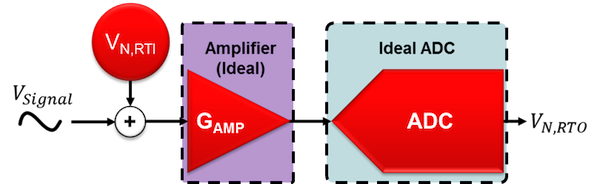
Figure 1. “Noiseless” components with one total input-referred noise source
However, this approach requires that you know the noise spectral densities for both the ADC and PGA, which are not common specifications in an ADC’s data sheet. Instead, you can actually forgo any calculations and simply look up the applicable input-referred noise in the ADC data sheet’s noise tables. This highlights one of the benefits of using ADCs with integrated amplifiers: The calculations discussed in part 6 are effectively completed by the ADC manufacturer, simplifying system noise analysis compared to using external amplifiers with an ADC.
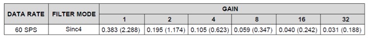
Therefore, the only action left is to choose the ADC’s settings. For this example, I will use the ADS1262 at an output data rate (ODR) of 60 samples per second (SPS) and a SINC4 filter – although the same methodology applies to any combination of data rates and filter types. Table 1 shows the input-referred noise values for the ADS1262 at these settings and across all available gains. I’ll use these values as the baseline input-referred noise throughout the remainder of this analysis.
Table 1. ADS1262 input-referred noise in µVRMS (µVPP) for ODR = 60SPS, SINC4 filter, TA = 25°C, AVDD = 5V, AVSS = 0V, VREF = 2.5V
Selecting an External Amplifier
Now that you understand how to determine the ADC’s input-referred noise, the next step is to select an external amplifier to compare to the baseline performance. Once selected, you can use a modified version of the single-amplifier noise model and the input-referred noise equation derived in part 6 to complete the analysis. Although you are actually evaluating a multistage amplifier circuit, you do not need to use the multistage amplifier model from part 6, since the amplifier noise from the ADS1262’s integrated PGA is included in the total input-referred noise reported in Table 1. Figure 2 shows the modified version of the equivalent noise model, while Equation 1 is the corresponding input-referred noise equation.
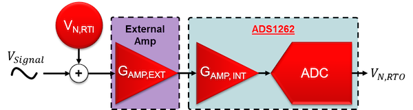
Figure 2. Modified equivalent noise model with ADS1262 ADC and PGA noise combined
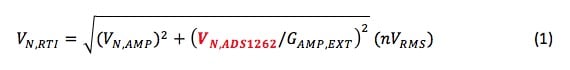
Equation 1
For this analysis, let’s choose the OPA141, OPA211, and OPA378. These three precision amplifiers’ dissimilar voltage-noise characteristics will demonstrate the benefits and challenges of each, but you can perform this same analysis on any type of external amplifier.
Calculating Amplifier Voltage Noise
The next step is to determine the noise voltage of each amplifier. To do so, you need the voltage-noise density plot and noise specifications for each, beginning with the OPA141 (Figure 3). The OPA141’s voltage-noise density comprises two distinct regions: a low-frequency (1/f) noise region, highlighted in red, and a flat (broadband) region highlighted in blue.

Figure 3. OPA141 table of noise parameters and voltage-noise density plot, with 1/f (red) and broadband noise (blue) highlighted
This non-flat noise density makes calculating the OPA141’s noise contribution a challenge. For narrow-bandwidth systems, 1/f noise will dominate, whereas wide-bandwidth systems will be much more dependent on the amplifier’s broadband noise. Therefore, to determine the amplifier’s noise contribution, you first need to calculate the system’s effective-noise bandwidth (ENBW).
Given the narrow bandwidth of the ADC’s digital filter at the chosen ODR, you can assume that the ADC’s bandwidth dominates the overall signal chain. In part 5 of this series, I calculated an ENBW of 14Hz using the ADS1262’s SINC4 filter at 60SPS (you could also approximate the ENBW using the filter’s -3dB point at this ODR). Using 14Hz as the system ENBW and overlaying it on the OPA141 plot as an ideal brick-wall filter will determine the amplifier’s noise contribution, highlighted by the purple region in Figure 4.
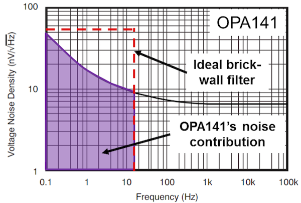
Figure 4. OPA141 voltage-noise spectral density plot with an ideal brick-wall filter at 14Hz
Since the ENBW is small, the OPA141’s noise comes almost entirely from the 1/f region. To determine the actual value of this noise, you can use direct integration or simplified formulas that estimate the area under the noise density curve. When performing these calculations, you’ll find that the OPA141 contributes 45nVRMS of noise into the system.
How does this compare to the next amplifier, the OPA211? Figure 5 shows the OPA211’s noise parameters as well as its voltage-noise spectral density curve, which has a similar shape compared to the OPA141. The purple region highlights the OPA211’s noise contribution given an ENBW of 14Hz.
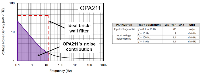
Figure 5. OPA211 voltage-noise spectral density plot and table of noise specifications
However, this purple region represents only 18.3nVRMS of noise contributed to the system by the OPA211 – considerably less than the OPA141. Therefore, you should never assume anything from the shape of the noise plot or the values in the amplifier’s noise tables. Instead, it’s very important to perform the necessary calculations before making any judgments regarding the noise performance of an external amplifier.
The third amplifier, the OPA378, has a different voltage-noise spectral density curve compared to the previous two, shown in Figure 6. Since the OPA378 is a chopper-stabilized amplifier, its noise spectral density curve is approximately flat, with no significant 1/f component. Therefore, you can use the data sheet’s voltage-noise density value (20nV/√Hz) to calculate that approximately 76nVRMS of voltage noise passes into the system, highlighted in purple.
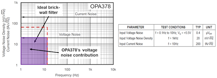
Figure 6. OPA378 voltage-noise spectral density plot and table of noise specifications
With the voltage-noise calculations complete, let’s add these amplifiers to the input of the ADS1262 and see how this impacts system noise performance. But before doing that, let’s a take a quick look at one other parameter captured in Figure 6: current noise.
A Point About Current Noise
Although the focus has been on voltage noise throughout Part 7, the OPA378’s noise-spectral density curve in Figure 6 includes a current-noise plot as well (in units of femtoampere per root hertz). Using the same ENBW from the voltage-noise calculations, you can calculate the OPA378’s current noise contribution as 759fARMS. While this value may seem insignificant compared to the OPA378’s voltage noise, recall that the cumulative effect of current noise depends on the input impedance that this component sees. Therefore, it is imperative to understand what input impedance causes the OPA378’s current noise to be significant.
Figure 7 plots input impedance versus the percentage increase of total noise (voltage plus current) using the OPA378, highlighting several different input impedances and their corresponding effect on total noise. For example, an input impedance of 14kΩ results in a current noise that increases total noise by 1% relative to voltage noise alone. Or, if you could afford a 10% increase in noise budget, your system could tolerate an input impedance of 46kΩ.
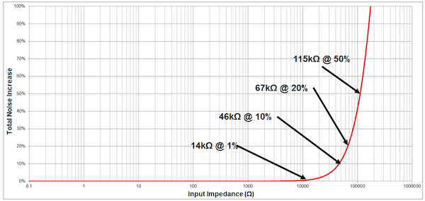
Figure 7. The percentage increase of OPA378 total noise (voltage plus current) as a function of input impedance
Therefore, current noise can be important when your signal-source/sensor output impedance is large. However, for typical sensor inputs such as resistance temperature detectors (RTDs) or resistive bridge circuits – whose impedance is generally ≤1kΩ – current noise would have very little impact on the total noise.
I will ignore current noise in this example under the assumption that the input impedance is small. However, a complete noise analysis always includes current noise calculations, at least to confirm whether they’re negligible.
Now, let’s complete the analysis by adding the external amplifiers to the input of the ADS1262 to compare the results.
External Amplifiers and Precision Delta-Sigma ADCs
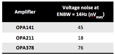
Table 2 summarizes the noise performance of the three different amplifiers analyzed thus far.
Table 2. Amplifier Voltage Noise Using ENBW=14Hz
To compare these external amplifiers against the ADC’s baseline performance, you can plot the input-referred noise as a function of gain for the ADS1262 using the data-sheet values. Then, using the information in Table 2, add each amplifier to the input of the ADS1262 and use Equation 1 to plot the total input-referred noise across all binary gain values up to 512V/V. Set the ADS1262 gain to 1V/V in all cases when using external amplifiers. Figure 8 depicts this plot.
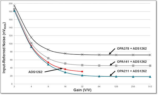
Figure 8. Input-referred noise as a function of gain for the ADS1262 alone and three external amplifiers plus the ADS1262
Figure 8 offers several interesting conclusions, most notably that the OPA378 and OPA141 actually increase the total input-referred noise – even at the highest gains – compared to using the ADS1262 alone, while the OPA211 decreases the overall system noise.
Additionally, all of the curves in Figure 8 begin to flatten at some gain; for example, at 16V/V for the OPA378 and at 64V/V for the OPA211. This transition point acts as a useful gain limit, or the point at which adding more gain has a negligible impact on input-referred noise performance (and therefore no value from a resolution perspective).
As I discussed in part 6, increasing gain results in the first gain stage dominating the overall input-referred noise equation (see Equation 1). At this point, the noise-versus-gain relationship essentially becomes constant. Even the ADS1262 by itself experiences this phenomenon at 32V/V, with the internal PGA becoming the dominant noise source.
In many circumstances, adding an external amplifier to the input of a high-resolution delta-sigma ADC will actually hurt your noise performance, as was the case with the OPA141 and OPA378. This is because ADC manufacturers optimize delta-sigma ADCs – and any integrated PGAs, if applicable – for precision and accuracy within a relatively narrow range of input signals. However, even precision amplifiers like those discussed in this article need to allow for a much wider range of input signals, making it more challenging to achieve the same level of performance.
When external amplifiers do improve noise performance, this improvement has a limit (as shown in Figure 8). Also, adding an external amplifier can impact other system performance metrics such as offset, gain error and drift, in addition to increasing cost, board space and power consumption.
Ultimately, it is imperative to carefully consider the purpose of amplifiers in the signal chain when using high-resolution delta-sigma ADCs. In some cases they may be necessary – attenuating high voltage inputs, for example – so understanding their effect on system noise is critical to a successful design.
In part 8 of the “Resolving the Signal” series, I’ll discuss the impact of reference voltage noise on the signal chain.
Key Takeaways
Here is a summary of important points to help better understand how amplifier noise affects delta-sigma ADCs:
- Know how to determine total amplifier noise.
- Consider the impact of current noise if the source has a high-impedance output.
- Integrated PGAs offer several benefits, including:
- Less math required when designing a data acquisition system.
- Optimization for resolution and accuracy.
- Higher gain does not always increase resolution; it depends on any amplifier(s) used, the ADC and the system ENBW.
- Amplifiers can impact other performance metrics in addition to noise (offset, drift, etc.).
Industry Articles are a form of content that allows industry partners to share useful news, messages, and technology with All About Circuits readers in a way editorial content is not well suited to. All Industry Articles are subject to strict editorial guidelines with the intention of offering readers useful news, technical expertise, or stories. The viewpoints and opinions expressed in Industry Articles are those of the partner and not necessarily those of All About Circuits or its writers.